EXAMPLES OF THE USE OF ANALYSIS PROGRAMS
1. Analysis of a building frame for deflection.
(FRAME-X.BAS)
2. Analysis of an Arch for Non-linear Effects
(FRAME-X.BAS)
3. Analysis of a Lamella grid system. (GRID-X.BAS)
4. Analysis of a Flat Slab using a grid program,
(GRID-X.BAS)
(Use of the program FRAME-X.BAS)
The structure is a building frame with two columns and three beams as shown in the sketch. This configuration may have excessive deflection for lateral loads and will be investigated for the nonlinear increase, (often called the P/Delta effect). The beams picked for analysis are W18x46, and the columns W8x31.
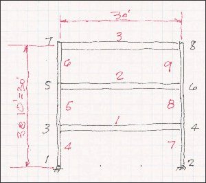
The first task is to lay out the joint numbers and the member numbers. The joint numbers should be arranged so that the difference between them is always the smallest possible to keep the solution time low, especially for large projects. The member numbers can be selected to keep similar members together. Note that the bases are shown as hinged.
The input to the program follows:
4000 DATA TEST BUILDING FRAME
1. Positive directions are down and to the left. (Opposite the "Right hand rule"), For stresses, the beam convention is used. tension on the bottom of the beam is possitive. The bottom is defined as if the member were horizontal, and the near end is to the left.
2. In this program, all dimensions are consistent. Feet and kips have been selected, so the value of E, the modulus of elasticity must also be in these units. The member properties must be in feet, also. For the output the deflection is in feet.
3.To exit from the member properties and the joint releases, a zero, (0), is added at the end of the inout
4. For the joint releases, a zero, (0), indicates fixity, and a one, (1), freedom to move.
On running the example you first see a print out of the input data so it can be checked again. There is also data generated by the program such as code numbers, (joint relations), which will also help to check the input. The loads are repeated as well as the loads generated by the program.
After printing the deflections and the shears and moments, it asks if you would like to continue with the iterations for the nonlinear analysis. As the iterations are made, keep you eye on the maximum deflection. When it no longer increases significantly, then the analysis is conplete.
The results are interesting, the initial deflection is 0.167 feet, 2.00 inches, and the final after five iterations is 0.197 feet, 2.36 inches, an increase of 16 percent. The moment in member 7 is 95.1 foot kips, and the final is 108.5 foot kips, and increase of 14 percent. A little high to overlook.
I leave it to you to decide what to do.
4010 '
4020 ' No. of members, no. of joints, value of E
4030 DATA 9,8,4.17E6
4040 ' Coordinates
4050 DATA 1,0,0, 2,30,0, 3,0,10, 4,30,10, 5,0,20, 6,30,20
4060 DATA 7,0,30, 6,30,30
4070 ' Member, area,I,shear area (zero) if not considered. (ZERO TO QUIT)
4080 DATA 1,.065,.00530,0, 2,.093,.03430,0, 0
4090 ' Member, from joint, to joint, member type.
4100 DATA 1,3,4,2, 2,5,6,2, 3,7,8,2, 4,1,3,1, 5,3,5,1, 6,5,7,1
4110 DATA 7,2,4,1, 8,4,6,1, 9,6,8,1
4120 ' Joint releases or supports. (zero for fixity, 1 to deflection)
4130 DATA 1,0,0,1, 2,0,0,1, 0
4140 '
4150 DATA 1, Lateral and Vertical
4160 ' No. of joint loads, No. of member loads
4170 DATA 3,3
4180 ' Joint loads: (Joint, X, Y, Moment)
4190 ' DATA 3,-4,0,0, 5,-40,0, 7,-4,0
4200 ' Uniform loads: (Member, X, Y)
4210 DATA 1,0,2, 2,0,2, 3,0,2
(Use of the program GRID-X.BAS)
The example used to illustrate this grid program is a timber lamella roof system. The maximum length of any member is always less than the span. In this case the maximum length is 12 feet and the span, 18 feet. Of course the span could be longer and the length shorter by using more of the basic patterns. A sketch follows with the joint numbers and member numbers. The positive directions are: X is down and Y is to the right.
In this program all dimensions are consistant, and inches and pounds were used. The joint numbers should be laid out so that there is the smallest difference between the number at one end and the number at the other. For the member numbers, I like to have similar numbers together. There should be hinges at the ends of each member, but it is easier to simplly make the torsional stiffness very small. You will find very small end moments in some cases. For this example, members made from 4 pieces, of 2x12's were used.
The input to the program follows:
3000 DATA LAMELLA FLOOR SYSTEM
3010 ' No. of members, No. of joints, Value of E
3020 DATA 12,11,1600000
3030 ' Coordinates: Member, X, Y
3040 DATA 1,0,144, 2,72,0, 3,72,72, 4,72,144, 5,72,216, 6,72,288
3050 DATA 7,144,72, 8,144,144, 9,144,216, 10,216,72, 11,216,216
3060 ' Member properties, No., I value, J value (zero to exit).
3070 DATA 1,760,0.1, 0
3080 ' Member incidences
3090 DATA 1,2,3,1, 2,3,4,1, 3,4,5,1, 4,5,6,1, 5,7,8,1, 6,8,9,1
3100 DATA 7,3,7,1, 8,7,10,1, 9,1,4,1, 10,4,8,1, 11,5,9,1, 12,9,11,1
3110 ' Supports and releases, Jt., vert, Mx, My (zero to exit).
3120 DATA 1,0,1,1, 2,0,1,1, 6,0,1,1, 10,0,1,1, 11,0,1,1, 0
3130 ' Load numb., Descrip., No. joint loads, No. member loads
3140 DATA 1,UNIFORM LOADS, 0,12
3150 ' Twelve uniform loads
3160 DATA 1,18, 2,33, 3,33, 4,18, 5,33, 6,33, 7,18, 8,18
3170 DATA 9,13, 10,13, 11,18, 12,18
3180 '