EXAMPLES OF THE USE OF DESIGN PROGRAMS

1.  Funicular Arch (D-FUNICU.BAS)
2.  Properties of a built-up angle (PROP-XY.BAS)


DESIGN OF A FUNICULAR ARCH

(Use of the program D-FINICU.BAS}

A sketch is shown in the attached drawing. It is a concrete arch with a span of 150 feet and a rise of 30 feet. The distance from the crown to the springing is 80.78 feet. It is a pedestrian bridge and the arch supports a steel girder of 75 foot span. The arch can be precast or cast horizontal and rotated into place. It is three hinged.
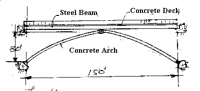

The steel beam supports a 4 inch concrete deck, 12 feet wide over sheet metal decking. The weight of the steel beam is assumed to be 100 plf. The live load is assumed to be 40 psf. The arch rib is assumed to be 16x30 inches. Design the arch for optimum stresses using the program to determine the coordinates of the arch.

The reaction of the steel beam at the center support for half the span is:
Dead Load   100x75/2 6x50x75/2
Live Load   40x6x75/2
Dead plus total live
Dead plus half live

= 15000 pounds.
=   9000 pounds
= 2400 pounds
= 19500 pounds

The arch will be designed for Dead plus half live, then the maximum moment due to live load should be the same for Dead only, as for Dead plus full live. The thrust will not be as large for the Dead only, so this is not the optimum loading but should be near.

The arch will be analysed for 6 segments each 75/6 = 12.5feet long, horizontally. The slope length is, approximately:

12x80.78/75=12.92,

so the weight of each segment is:

12.92x16x30x150/144=6460 pounds each.

The center load is 6460/2+19500=22730 pounds.

These values were entered into the program D-FINICU.BAS, and the following coordinates for the arch were obtained for Y:

0,0.00; 1, 7.12; 2 13.39; 3 18.82; 4,23.34; 5,27.28; 6, 30.00.

The center coordinate is 18.82, so the rise above the diagonal is 18.82-15=3.82.

The arch can now be analysed designed, reanalysed, redesigned, etc.


PROPERTIES OF A BUILT-UP ANGLE

(Use of the program PROP-XY.BAS)

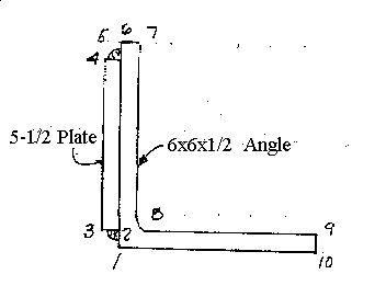
A compression member, a 6x6x1/2 is inadequate for compression. The only way ro increase its capacity is to add a plate on the side as shoen in the sketch. The radius of gyration from the AISC Manual is 1.18 inches. What will be the new value of the the radius of gyration?

Enter the coordinates of the program basec on the numbering system shown in the sketch, and run the program. The coordinates as they are entered are:

1,0.5,0, 2,0.5,0.5. 3.0,0.5, 4,0,5.5, 5,0.5,5.5,
6,0.5,6, 7,1,6, 8,1,0.0, 9,6.5,0.5, 10,6.5,0

The result for the smaller moment of inertia, I, is 11.01, and for the are, A, is 8.25 si. The radius of gyration is equal to the SQR(I/A) = SQR(11.01/8.25) = 1.16. The only gain has been in the available area.