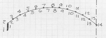
The barrel shell to be described is that in the set of programs SHELLS.zip, which may be downloaded from this web site. It is a single barrel with an edge beam on the left and the valley it is a section of symmetry. so the analysis is for two barrels.
Layout of joints and members is shown in the sketch. The shell is divided into 12 equal angle members plus the edge beam.

The dimensions that must be used are feet for distances, and pounds for weights. The resulting deflections and stresses are as noted in the output. The coordinates and dimensions were created by the program, CIRCLES.BAS which is also included. These same values are given for the built-in example. Dimensions and loads are as follows:
Span = 60 ft., Width=30 ft., Rise=6.5 ft
The radius is 20.55 ft., and the end slopeis 46.86 degrees.
This is about the maximum suitable slope of a shell.
Shell thickness=0.29 ft (3.5 in.), Edge beam 1ft.x 3 ft.
Length of shell segment=2.802 ft.
Weight of concrete=150 pcf, Weight of one segment=122.9
Snow load, (per length of segment)=25 psf. One segment=71.4 p
Extra load has been placed at the valleys to compensate for the in-fill.
Input for the program is listed at location 5,000 as follows:
5000 DATA SINGLE BARREL WITH EDGE BEAM
The following should be noted:
1. At location 5030 and 5040. If the joint numbers are in sequence, then you do not need to list them. In the case of an interior beam where the joint numbers are not in sequence then theymust be listed aand 5040 would be: N (for no).
2. The loads at 5190 require a zero (0) to end the input..
3. You can eliminate the Z (longitudinal stiffness) in a member listing a zero (0) in location 5130, so you can simulate a column to support an edge. This was not used in this example.
4. In 5070 the special supports are listed. The only one is the symmetrical joint, 14, at the valley. Use one (1) for free and zero for fixity. It is fixed for moment and a force in the X direction, free for vertical deflection.
5. Note that loads can also be in the X direction.
When you run the program the following should be noted:
1. The program repeats the input and then generates other information very useful for checking, such as equation numbers and summation of loads.
2. If you wish to continue after the initial results, the program will continue a nonlinear analysis simply by sucessively revising the coordinates by the deflections. Usually this does not result in much change in a barrel shell, but is useful in making stability studies.
Some of the results of running the program are as follows:
1. The maximum deflection is at Joint 1 and equals 0.289 inches. Considering that this joint is at the base of the edge member, this deflection should be satisfactory. If the edge member were smaller, then one should support the edge with intermediate columns. The deflection at Joint 12 is 0.217 inches.
2. The maximum stress is + 628.38 psi at Joint 1. This, of course, must be translated into reinforcing steel. At the valley the stress is 577.47 psi.
3. The maximum bending moment is - 425.53 pounds, (tension in the upper fiber), at joint 14
The deflections and stresses seem to be well conditioned and satisfactory.
5010 ' Span, E, No. of members, No. of joints
5020 DATA 60,432E+6,13,14
5030 ' Generate member/joint relations (Y?N) ?
5040 DATA "Y"
5050 ' Member/joint relations: Member, X joint, Y joint.
5060 ' Special supports: Joint, X, Y, Z, Phi, (0 to exit)
5070 DATA 14,0,1,1,0, 0
5080 ' Member, thickness, Special I value, (0 for no special value)
5090 DATA 1,1.00,0, 2,.290,0, 4,.290,0, 4,.290,0, 5,.290,0, 6,.290,0
5100 DATA 7,.290,0, 8,.290,0, 9,.29,0, 10,.29,0, 11,.29,0, 12,.29,0
5110 DATA 13,.29,0
5120 ' Do some members have no longitudinal stiffness, (List number)
5130 DATA 0
5140 ' Coordinates: Joint. X, Y
5150 DATA 1,0,0, 2,0,3, 3,2.047,4.908, 4,4.339,6.520, 5,6.826,7.805
5160 DATA 6,9.465,8.741, 7,12.207,9.309, 8,15.000,9.500
5170 DATA 9,17.79,9.31, 10,20.53,8.74, 11,23.174,7.805, 12,25.66,6.52
5180 DATA 13,27.951,4.908, 14,30,3
5190 ' Loads: Joint, X, Y, (0 to Exit)
5200 DATA 1,0,225, 2,0,322, 3,0,194, 4,0,194, 5,0,194, 6,0,194
5210 DATA 7,0,194, 8,0,194, 9,0,194, 10,0,194, 11,0,194, 12,0,184, 0