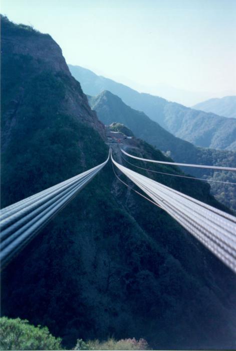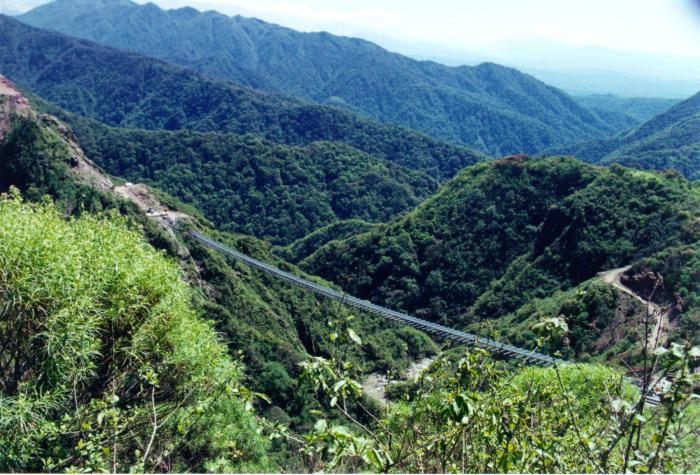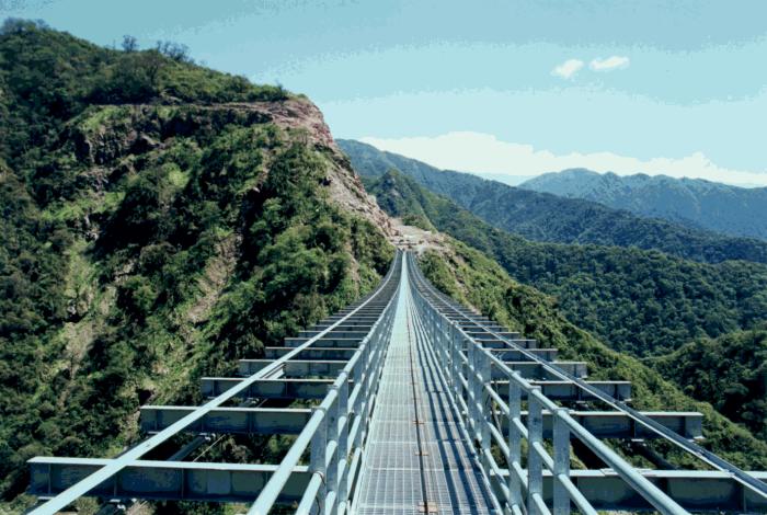
Fig. 1: The Arroyo Cangrejillo Pipeline Bridge
Arroyo Cangrejillo Pipeline Bridge, Catamarca, Argentina
Mark A. Ketchum, Ph.D., Vice President
Francis Drouillard, Principal
James Scheld, Engineer
OPAC Consulting Engineers, Inc., San Francisco, CA U.S.A.
Introduction
The Arroyo Cangrejillo Pipeline Bridge (Fig. 1) carries a copper concentrate pipeline and a foot path across a deep valley in the mountains near Las Estancias, Argentina. The pipeline extends from a new gold and copper mine north of Andalgala to a rail facility in San Miguel de Tucumán. Construction of the bridge saved the waterfalls and crab ponds of the rainforest valley from the environmental impact of a burried pipe and service road.
Fig. 1: The Arroyo Cangrejillo Pipeline Bridge
Several structural systems were developed and evaluated prior to selecting the cable supported steel grillage that was built. These included a classical suspension bridge, multi-span girders, a delta truss, and a freely hanging pipe. The cable-supported grillage was selected based on its economy, rapid construction schedule, aerodynamic stability, and ability to carry a widened foot path should the need arise.
Design
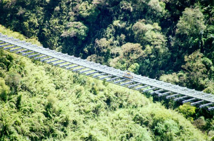
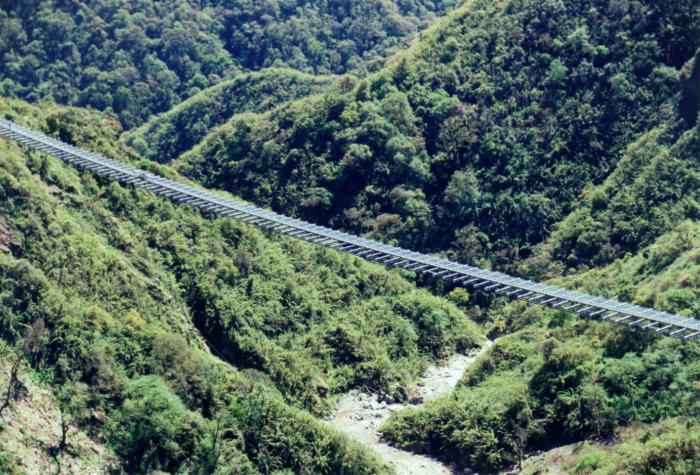
The 337 m single span bridge carries a 1 m wide foot path and 0.2 m diameter pipe across a rugged 90 m deep valley. It is an unstiffened suspension structure, with cables that support directly the open steel deck framing. The vertical alignment of its deck follows the drape of the cables, which sag 7.85 m (equivalent to 2.3% of the bridge length) at mid span.
The structural components of the bridge include two pairs of cables, anchored in reinforced concrete abutments, that support the ends of 8 m long floor beams. These beams in turn support the pipe and stringers for the foot path (Figs. 2 + 3). As the unbraced steel grillage does not stiffen the bridge, all vertical and lateral loads are resisted by the cable system.
The design allows for future widening of the deck to 3 m to allow use by a 2-t truck. The widening would require adding two more cables, and extra stringers and decking.
The bridge was designed according to the specifications of AASHTO (Standard Specifications for Highway Bridges) and INPRES-CIRSOC (Normas Argentinas Para Construcciones Sismorresestentes). The design loads given in Table 1 were considered.
Table 1: Design Loads
| Cables | 1.88 kN/m | ||
| Steel Framing | 4.25 kN/m | ||
| Pipe and Miscellaneous | 0.70 kN/m | ||
| Copper Concentrate | 0.34 kN/m | ||
| Pedestrian | 4.07 kN/m | ||
| Nominal Temperature | 15° C | ||
| Temperature Rise | 33° C | ||
| Temperature Fall | 35° C | ||
| Wind (130 kph) | 2.10 kN/m | ||
| Seismic (T = 3.6 sec) | as = 0.16g |
Abutments
The abutments provide a secure anchorage for the bridge cables at the ends of the span. They are reinforced concrete blocks, cast directly against a benched and keyed rock surface (Fig. 3). Each abutment is secured to the underlying rock with 24 or 28 post-tensioned rock anchors (Fig. 4). Each rock anchor consists of 11-15mm diameter strands of 30 to 60 m length, installed at a 1:1 batter.
The abutments and rock anchors were designed to maintain a state of nominal compression in the rock under all service conditions. Changes in bridge cable forces under expected service loads were found to introduce large shears where the abutment bears on the rock. Therefore shear keys were provided in the rock, allowing the rock anchors to remain under a fairly constant stress.
Ducts for the bridge cables were formed by casting 324 mm diameter straight steel pipes into the anchorages. Free access to the back wall of the abutment allows installation and adjustment of the cables.
Cables
The four main cables carry all loads to the abutments. They are comprised of the Freyssinet prestressing strand and anchor system developed for use in cable-stayed bridges. Each cable consists of 37-15mm diameter strands; each 7-wire galvanized strand is enclosed within a wax filled HDPE sheath. This system provides adequate corrosion protection without a common cable duct, thus permitting the installation, removal, or replacement of individual strands.
The strands are bundled into a hexagonal shape by cable bands that also serve to secure the floor beams to the cable (Fig. 5). Friction between the cable bands and the strand, through the sheaths, was considered inevitable but unreliable. Therefore, the bridge was designed to perform adequately both with and without the effects of this friction.
The drape of the cables under structural dead load at a nominal temperature of 15°C is 7.85 m. Under the influence of live loads, temperature changes, and other transient effects, the drape is expected to vary between 6 m and 12 m. The range in drape results in a significant angle break at the face of each abutment. Cable deviators and anchorages were provided at the abutments to accommodate the anticipated angle break during construction and under service conditions, as well as fatigue conditions, without distress to the cable.
The anchorage deviator on each cable consists of a neoprene insert in the anchorage duct. It performs three essential functions. First, it confines the individual strands into a parallel bundle as the cable enters the anchorage assembly. Second, it permits an angle break of ± 4.1°. Third, it alleviates fatigue stresses on the anchor head and at the strand anchor wedges.
Deck Framing
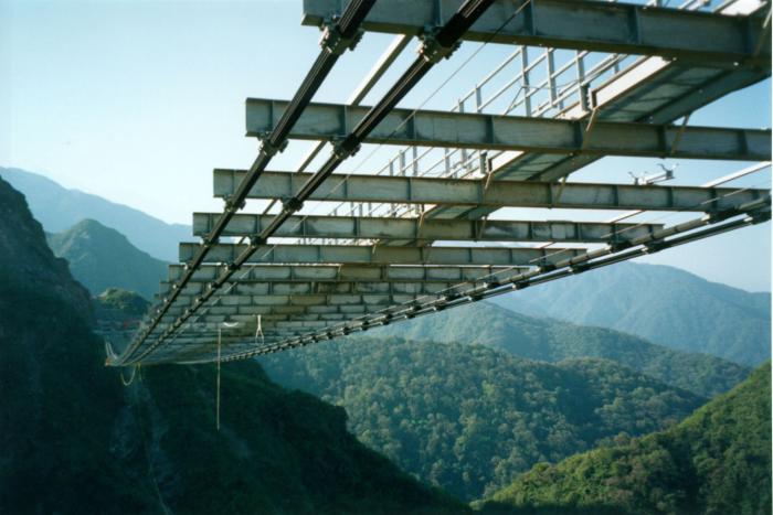
The steel deck framing serves to tie the cables together and distribute the loads from the foot path and the pipe to the cables. Material delivery and equipment access issues at the site dictated light erection equipment and therefore relatively small framing segments. Principal components include IPE330 transverse floor beams spaced at 2.5 m along the cable, and simply supported UPN200 stringers to frame the foot path (Fig. 6).
The floor beams are clamped to the cables using bent steel plate cable clamps that are bolted to the bottom flanges of the floor beams. The deck stringers are bolted to the top flanges of the floor beams, with additional diagonal braces to the bottom flanges, to restrain lateral-torsional buckling of the floor beams. Additional lateral-torsional buckling restraint is provided by bridging diaphragms near the ends of the floor beams. These diaphragms are provided in every 20th floor beam bay, and are connected to intermediate floor beams with continuous longitudinal bracing at the top flange.
Diagonal bracing in the plane of the deck framing was not provided. Design studies showed that it would provide only marginal stiffening, since the highly tensioned cables are so efficient at resisting loads and deformations.
Quantities
| Main Cables | 57 tons | ||
| Structural Steel | 129 tons | ||
| Reinforced Concrete | 250 m3 |
Design Specifications
"Standard Specifications for Highway Bridges,"AASHTO, 16th ed. 1996.
"Normas Argentinas Para Construcciones Sismorresistentes," INPRES-CIRSOC, Nov 1983.
Allowable Stresses
| Main Cables | f = 0.45Fy | ||
| Rock Anchors | f = 0.60Fy |
Analysis
Analytical studies of the bridge were performed to support the proportioning of its components and to demonstrate its structural adequacy under construction, service, and extreme-event conditions. These studies included static evaluation of the cables under vertical and lateral loads, three-dimensional frame modeling for static and dynamic response, and wind evaluation to validate the design with respect to stiffness and stability.
Cable Analysis
The cable analyses focused on estimating the forces in the cables and the distortions in the deck grillage under vertical and lateral loads. They made use of nonlinear cable theory to satisfy static equilibrium and displacement compatibility in the deformed position of the cable.
Cable tension and cable sag are influenced by loads, temperature, and the initial stresses and position of the cable. Both the cable force and sag increase as the loads on the cable increase, and their product is directly proportional to the loads. The force equations and geometry equations for various loadings were programmed and solved iteratively in a spreadsheet computer program.
The governing static loading condition for the completed bridge was dead load plus live load combined with temperature decrease. Static wind load was found to cause the bridge to sway, with some distortion of the grillage but with little increase in cable force. The critical issue for construction was found to be the angle change in the cable at the abutment as the bare cable was loaded and deflected.
Dynamic Analysis
Dynamic analysis was used in evaluating seismic and wind response. It made use of a three-dimensional frame model of the bridge, linearized about the at-rest configuration of the bridge by incorporating the tension stiffening of the cables at their dead load geometry and stress levels.
The influences of friction and slippage between the floor beams and the cables were evaluated using bounding studies. Models based on the bounding assumptions of 1) no friction, 2) no slippage, and 3) flexible connection were evaluated. The loads on the floor beams were quite different for the various cases, however the dynamics of the bridge changed very little.
The fundamental frequencies of the bridge were estimated as follows:
| Lateral | 0.27 Hz | ||
| Vertical | 0.39 Hz | ||
| Torsional | 0.48 Hz |
Wind Studies
Wind engineering studies provided estimates of the stresses, deformations, and aerodynamic stability of the bridge in strong winds. A semi-empirical approach made use of wind tunnel tests of a section model along with computer models of mechanical characteristics. The studies considered wind speeds ranging up to 130 kph.
Conclusions of the wind studies were:
The benign wind performance of the bridge is attributable to its open grillage, fully ventilated deck, and its widely separated highly tensioned cables. The closely spaced fundamental vibration modes did not cause any unresolvable problems.
Construction
The Arroyo Cangrejillo bridge was built using a modern adaptation of the centuries-old methods used by the Incas for the construction of straw rope suspension bridges in the Andes:
Construction of the abutments began in September 1997. Installation of the rock anchors was completed in July 1998 after several months of delays due to bad weather and the need to stabilize and clear the slopes of loose rock.
Erection of the main cables began in September 1998. A pilot cable was used to guide the installation of the final strands, which were individually adjusted to a predetermined profile and force (Fig. 7).
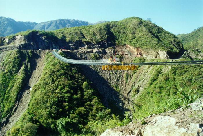
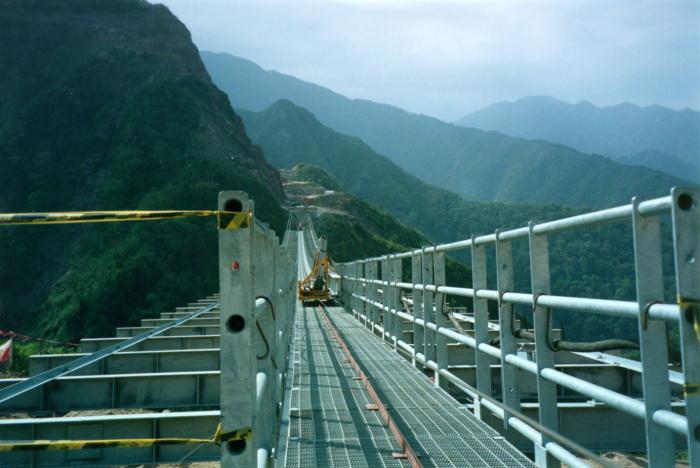
The structural steelwork of the deck was erected using special equipment designed by the construction contractor, Albano. The equipment consisted of winches mounted at the abutments, a light deck-mounted crane, a two-piece movable platform suspended from the main cables, and a rail guided cart to transport framing components from the stockpile at Front 2 to their final position on the bridge.
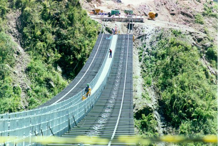
Once delivered to the working face of the steelwork by cart (Fig. 8), the pieces were picked and hoisted into position with the deck-mounted crane, then bolted into place by workers on the movable platform (Fig. 9). After the new segment was erected, the crane and platforms were moved along the cables and readied for the erection of the next segment. The cart was returned to Front 2 for another load while workers tightened bolts and advanced the crane and platform.
Up to 9 complete floor beams and associated framing sections were completed per day (Fig. 10), and the entire operation was completed in 6 weeks. The final framing segment was placed on October 24, 1998 to complete the span.
Conclusions
A structural form inspired by the straw rope suspension bridges of the Incas was adapted to modern construction materials to provide an efficient, economical, and functional bridge in the mountains of Argentina. It makes use of the established materials of modern cable-supported bridge construction, applied to a structural system that is particularly adapted to the site. Construction of the bridge saved a series of waterfalls and a pristine rain forest valley from the environmental devastation that would have ensued if an at-grade solution had been built.
Credits
| Owner | Minera Alumbrera Ltd. | ||
| Designer | OPAC Consulting Engineers | ||
| Wind Analysis | West Wind Laboratory | ||
| Contractor | Albano | ||
| Cables & Anchorages | Freyssinet | ||
| Service Date | October 1998 | ||
| Photos | Charles Lamb, Francis Drouillard, Mariano Mantel, and Laura Albano. |
November 18, 1998