THE DESIGN OF THE RUCK-A-CHUCKY BRIDGE
by T.Y. LIN and D. ALLAN FIRMAGE
Figures
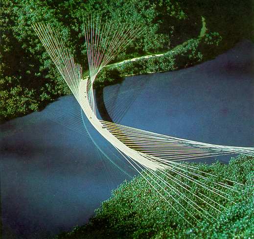
Fig. 1. Proposed Design of Ruck-A-Chucky Bridge
Fig. 2. Plan View of Cable Layout
Concrete Girder Design

Fig. 3. Elevation View of Cable and Girder
Concrete Girder Design
Fig. 4. Cross-section of Concrete Girder

Fig. 5. Cross-section of Steel Girder

Fig. 6(a). Erection Sequence
First Girder Segment Erected on Falsework

Fig. 6(c). Erection Sequence
Bridge Closed with Erection of Element 14 (Steel Girder)
Fig. 7. Use of Horizontal Erection Cables
to Reduce Horizontal Bending Moment (Mh) in Girder