 |
Wind Tunnel Tests of the Third Carquinez Strait Bridge |
|
Wind Tunnel Tests of the Third Carquinez Strait Bridge |
|
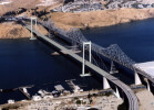
The 3rd Carquinez Strait Bridge
The 3rd Carquinez Strait Bridge will replace the original bridge that was built in 1927. The new suspension bridge will have a 728 m main span, a closed cell orthotropic steel deck, air-spun cables, and concrete towers. It was designed by Caltrans and the De Leuw OPAC Steinman Joint Venture. Wind tunnel tests were performed by Dr. Jon D. Raggett at West Wind Laboratory. |
|
The wind engineering studies performed to support the design provide a good example of a modern semi-empirical approach to wind engineering of a flexible structure. The objectives of the studies were to provide a bridge that is both safe and serviceable. The serviceability wind event has a return period of about 150 years, with a wind speed at deck level of about 110 mph. The aerodynamic stability event has a return period of 5,000 to 10,000 years, with a wind speed at deck level of about 155 mph. Stability in this event assures that the failure mode associated with the serviceability event is associated with strength, not stability.
Wind tunnel testing made use of section models as well as full bridge models. Click on the links or the images below for a higher resolution image. | |
|
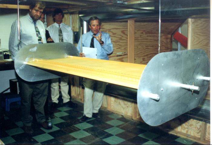
Section Model from Above
The section model is a large scale (1/50th) that captures the aerodynamic influence of the shape of the bridge. Mechanical properties are not modeled. It is big enough so that significant features can be modeled. The end plates provide a symmetry boundary condition to the model. |
|
|
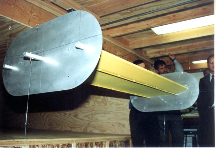
Section Model from Below
The streamline-shaped girder is intended to eliminate flutter instability. The maintenance platform rails underneath, and the guard rails on top, are essential to model. Without these features, the bridge performance would be quite different. |
|
|
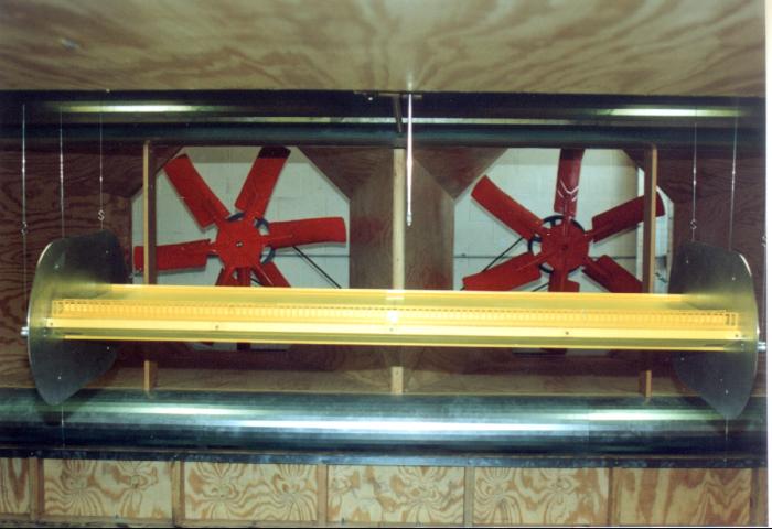
The Throat of the Tunnel
Air is pulled across the model, rather than pushed, to avoid uncontrolled turbulence in the wind. If turbulence is desired, then devices are placed upstream of the model to generate controllable, measurable, and repeatable conditions. |
|
|
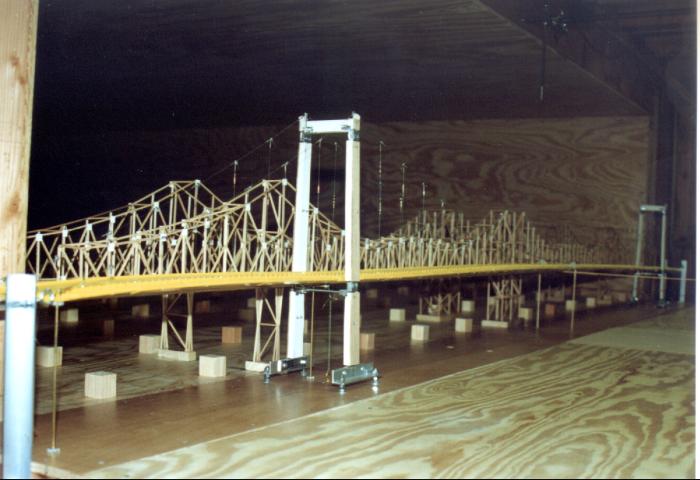
Full Bridge Model Side View
The full bridge model captures the influences of turbulence and the spatial distribution of the wind. It is not used directly to predict wind performance, because its scale is smaller than desired to model essential features. It must capture the influences of both shape and mechanical properties of the bridge. |
|
|
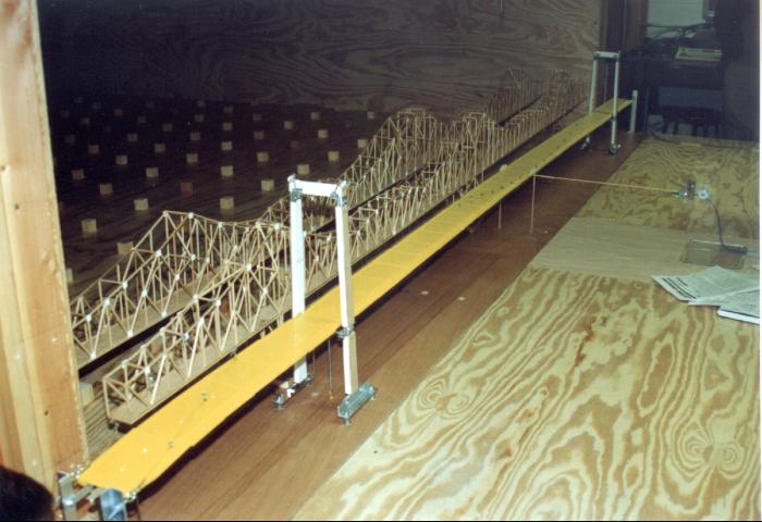
Full Bridge Model from Above
The existing bridges, and the turbulence generating blocks behind, allow the investigation of turbulence effects. Tests were made with and without these features. When the wind blows on the new bridge from behind the existing bridges, the new bridge moves less than when the existing bridges are removed. |
|
|
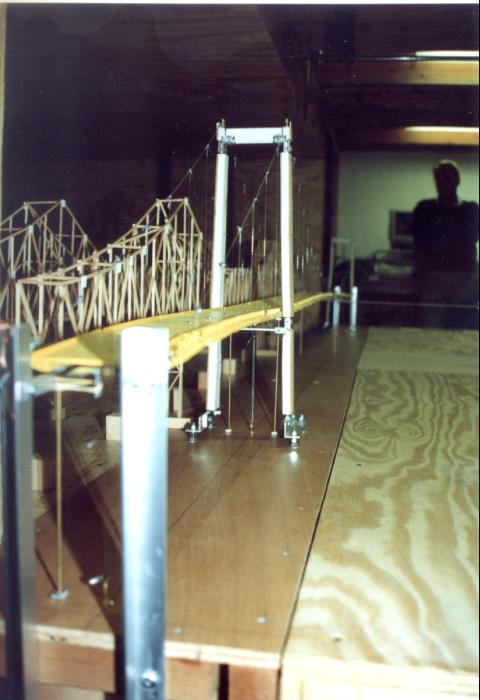
Full Bridge Model Scaling
The model is built differently from the prototype, since mass, stiffness, and length scale at different rates. Masses were clamped on to the cable, and the girder shape was articulated with springs, to provide adequate similarity with the prototype. |
|
|
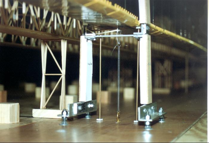
Full Bridge Model Articulation
The tower stiffness is modeled with slender aluminum shapes, then its shape is provide with cladding. The articulation of the girder at the tower was also modeled accurately, to simulate the vertical, torsional, and lateral constraint of the girder by the tower. |
|
|
The final estimation of wind performance makes use of static and dynamic finite element computer models along with the results of these wind tunnel tests. Vortex shedding, buffeting, galloping, and flutter of the girder are considered, under both smooth and turbulent flow.
Caltrans also maintains web pages concerning this bridge. So far I've found this one, this one, this one, and this one. | |