 |
Mark Ketchum's Carquinez Strait Bridge Page |
|
Mark Ketchum's Carquinez Strait Bridge Page |
|
The 3rd Carquinez Strait Bridge
The 3rd Carquinez Strait Bridge will replace the original bridge that was built in 1927. Additional web resources on the Carquinez Bridge that I know about are at Caltrans, Parsons, the Al Zampa Bridge Celebration Committee, the construction contractor HBG Constructors, Union Ironworker Dick McCabe Jr., the Metropolitan Transportation Commission, and a live webcam by Ed Tannenbaum. Check them out! |
by
Mark Ketchum, P.E., Ph.D.
OPAC Consulting Engineers, Inc.
San Francisco
(served the design team as Bridge Design Manager, Engineering Consultant, and Lead Engineer for Performance Assessment at various stages of design and construction of the bridge)
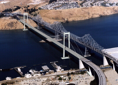
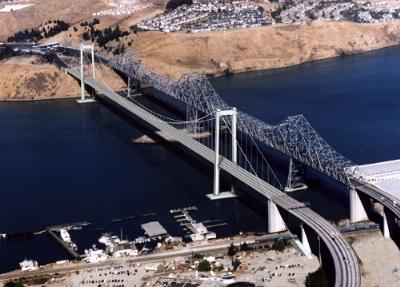
The Carquinez Strait, located about twenty miles northeast of San Francisco, carries the Sacramento River into San Francisco Bay. The strait is currently spanned by two steel truss bridges, built in 1927 and 1958, that provide a vital link on the Interstate Highway 80 corridor.
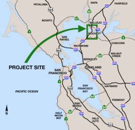
Heavy traffic on I-80, along with the infeasibility of adding lanes to the existing bridges, led to planning and engineering studies for a third bridge. Regional Measure 1, a 1988 ballot initiative in the San Francisco Bay Area, implemented higher bridge tolls to fund various projects including a new bridge at this site.
The Third Carquinez Strait Bridge is a major new structure in the San Francisco Bay Area that has been designed and built without attracting very much attention from the press or the public. This document provides some background on the project, explains the selection of a suspension structure for the new bridge, and introduces the major structural features of the new bridge.
The new bridge is a major engineering and construction accomplishment. It brings many "firsts" to the region, the bridge engineering profession, and the bridge construction industry:
Superlatives tell only part of the story. Here is some more:
The bridge carries Interstate 80 across the waters of the Sacramento River between Crockett and Vallejo, California. The site has long been a transportation link between the Bay Area and Sacramento. Private ferry service was initiated there in 1917. Bridges came a few years later.
The first Carquinez Strait Bridge was completed in 1927, owned and operated by the private American Toll Bridge Company. U.C. Berkeley Dean of Engineering Charles Derleth, Jr. was Chief Engineer; D.B. Steinman was Designing Engineer. The State of California took over the bridge in 1940. The second Carquinez Strait Bridge was completed in 1958, designed by the California Division of Highways. It is similar in layout to the first bridge, but incorporated many advancements including the use of welded high-strength steel. |
Increasing traffic and deteriorating structural condition prompted funding for replacing the 1927 bridge to be included in Regional Measure 1, a 1988 ballot measure for transportation funding that was approved by the Bay Area Electorate.
The replacement project was placed on an accelerated schedule when engineering studies performed under the statewide Seismic Program identified a very high retrofit cost for the aging structure.
Initial studies by Caltrans indicated that a three-tower cable stayed bridge was suitable for the site. JMI was engaged by Caltrans in 1992 to develop a preliminary design and cost estimate. JMI's concept is illustrated here in a Caltrans-prepared rendering. It has two 1175 ft (358 m) main spans, and two 500 ft (152 m) side spans, with A-frame concrete towers and concrete box girder deck. |
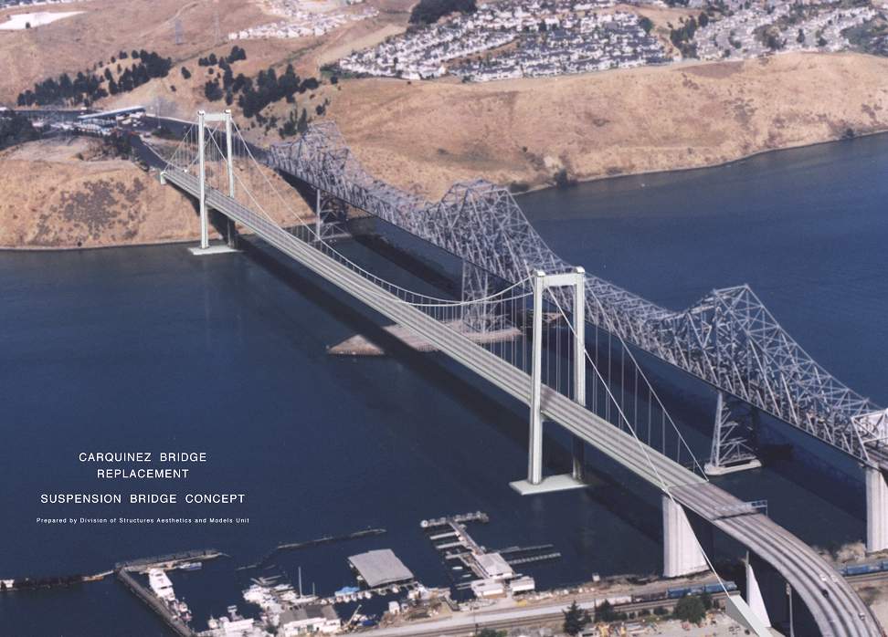
In an unsolicited structural concept study delivered to Caltrans in early 1996, OPAC Consulting Engineers suggested that a three-span suspension bridge may also be well suited to the site, and could have some advantages over the cable stayed options. OPAC's report included a suspension bridge design concept and a rough cost estimate. OPAC's concept is illustrated here in a Caltrans-prepared rendering. It has a 2350 ft (716 m) main span, and 500 ft (152 m) side spans, with batter-leg concrete frame towers and a steel box girder deck. |
During the spring and summer of 1996, Caltrans (with NCG and OPAC) evaluated several structural options for the new bridge. In addition to the Cable Stayed and Suspension options, two new alternatives were added: an Arch and a Truss.
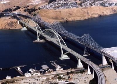
The arch alternative had a structural span arrangement a lot like the existing bridges, with two main spans of about 1,100 feet, supported by a central pier. The arch configuration is called "basket handle" because the curved arch ribs lean together as they extend above the roadway deck. This provides a very light and efficient structure. |
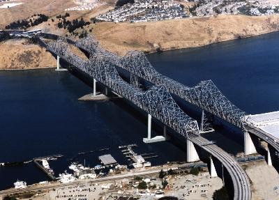
The truss concept was architecturally similar to the 1958 bridge. It had two main spans of about 1175 ft (358 m) supported by a central pier, and 500 ft (152 m) side spans. The piers were concrete portal frames. |
The cable-stayed and suspension bridge options were further developed during this period, to incorporate a wider deck and structural changes to enhance economy and performance. An orthotropic steel deck suspension bridge and a concrete deck cable stayed bridge were identified as the preferred alternatives.
In late 1996, the DeLuew-OPAC-Steinman Joint Venture was selected by Caltrans to complete the structural type selection studies and design the selected bridge. DeLuew and Steinman were at the time separate units of Parsons Corporation, OPAC is an independent consulting engineering firm. The Joint Venture was directed by Caltrans to prepare 35%-complete designs and cost estimates for suspension and cable-stayed bridges to support final type selection by Caltrans.
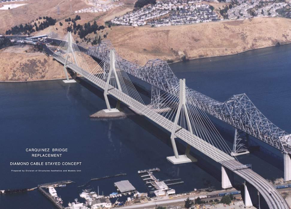
The final cable-stayed option had three diamond-shaped concrete towers and a concrete box girder deck. Stay cables would radiate outward and downward from the tops of the towers to support the deck. |
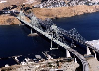
The final suspension bridge option had two batter-leg concrete frame towers and an orthotropic steel box girder deck. Classic draped cables and vertical suspender ropes would support the slender aerodynamically streamlined deck. |
The suspension bridge alternative was selected for final design and construction, based on superior seismic performance, shorter construction schedule, less risk of ship impact due to fewer number of piers in the water, less maintenance on cable system, better aesthetics, and less construction risk. Projected construction costs for the two alternatives were quite similar.
The suspension bridge design has a main span of 728m to provide the required navigation clearance in the north and south channels. The south side span is relatively short (147m) to allow the south transition pier to clear the railroad tracks. The north side span is longer (181m) to clear a slide zone and fault in the cliff. |
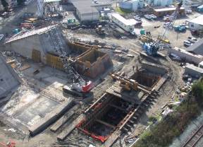
The towers are supported on 3m diameter shaft piles. Steel casings were driven through overburden and into the top of the rock. Then an uncased rock socket was drilled below the casing. The rock socket and casing were then reinforced and concreted. Each tower is supported by twelve such shafts, with a maximum length of about 90m. |
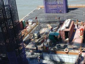
Reinforced concrete pile caps with precast concrete shells transfer vertical and lateral loads between piles and tower, and provide platforms for construction of the tower shafts. Each of the four pile caps is about 22m x 18m in plan, and 6m thick. Heavy reinforcement is required for long-term durability and for seismic resistance. |
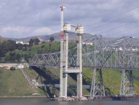
The towers are reinforced concrete portal frames with cellular shafts. The slightly inclined shafts allow clearance for the width of the continuous steel deck girder, yet allow the main cables to hang straight to support the edge of the deck. The tied walls and hoop-reinforced corner pilasters were specially developed to meet stringent seismic criteria. |
The south transition pier supports the end of the steel deck girder, houses tie-downs that divert the geometry of the cables to the south anchorage, and supports the end of the south viaduct. It is structurally and architecturally similar to the main towers, with cellular reinforced concrete shafts and pile foundations. |
The south cable anchorage transfers the thrust of the cables to the ground via massive concrete anchor blocks and a combination of batter piles and vertical piles. The splay chambers rise 18m above ground, while the anchor blocks extend about 10m beneath the ground surface. |
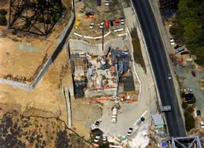
The north cable anchorage transfers the thrust of the cables to the ground by direct bearing on the underlying rock, and also serves as a bridge abutment. The concrete anchor blocks and splay chambers are benched into the rock beneath the roadway; only the relatively small saddle housings are exposed. |
The cables carry all loads from the deck to the towers and the ground. It was spun and compacted in the air from individual wires, using a computer-controlled spinning method that is an evolutionary enhancement of the method used on the Bay and Golden Gate bridges. |
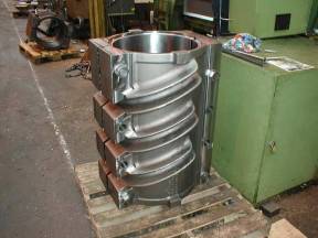
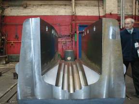
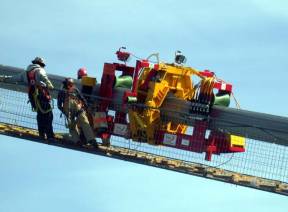
Steel castings transfer loads to the cables from the vertical suspender ropes, and transfer loads from the cables to the tops of the towers. Splay castings confine the cables in the anchorages. |
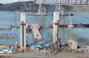
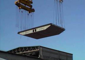
The suspended superstructure consists of a 1056m long closed steel box girder, continuous from the north anchorage to the transition pier at the south, supported along its edges by suspender ropes. The box girder is 3 m deep and 29 m wide. The edge plate and side plates are shaped to provide an aerodynamically stable cross section. The orthotropic deck of the girder consists of a 16 mm deck plate with 305 mm deep trapezoidal closed ribs fabricated from 8 mm thick plates. |
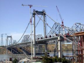
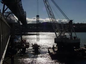
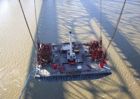
The deck girder was fabricated in segments in Japan, transported to the site on ships, and hoisted into final position using strand jacks. After all segments were in place, they were welded together to provide the final continuous ribbon of steel.
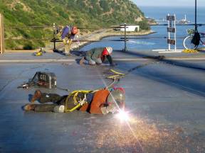
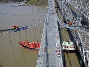
After the girder was completed, the structure was essentially complete. There were still, however, many construction tasks remaining. These included but were not limited to wrapping and painting the main cables, installing the deck railings and pavement, and making a driveable highway and functional footpath. |
The design of the bridge was supported by numerous in-depth engineering studies. Two of the studies deserve special recognition: wind and seismic.
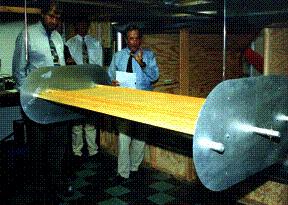
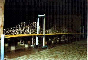
The bridge was designed for two levels of wind storm: a “Strength Event” with 100 year recurrence and 1-hour averaged velocity of 47m/s (105 mph), in which the bridge is not overstressed, and a “Stability Event” with 10,000 year recurrence and 10-min averaged velocity of 70m/s (157 mph), in which the bridge is to remain stable (no flutter or galloping). Wind engineering included tests of section and full-bridge models. |
Seismic design of the bridge conforms with the latest knowledge of seismicity and structural performance. The site is influenced by the San Andreas, Hayward, and Franklin Faults. Controlling ground motions are from the Franklin Fault. Two levels of earthquake were considered: a Functional Evaluation Event, with a 300 year return period in which no damage & no permanent offset is allowed, and a Safety Evaluation Event, with a 1000 to 2000 year return period in which only repairable damage with no traffic impact is allowed. Seismic performance of the bridge was validated by comprehensive inelastic computer modeling under propagating incoherent wave fields from a suite of earthquakes, and verifying that stringent limits on strains in concrete, rebar and structural steel were not exceeded. |
| Structural Steel | 12,722,000 Kg | (14,000 T) |
| Cable Steel | 4,600,000 Kg | (5,060 T) |
| Structural Concrete | 26,580 M3 | (31,770 CY) |
| Reinforcing Steel | 4,662,000 Kg | (5,130 T) |
| 3 M Concrete Piling | 996 M | (3,300 ft) |
| 2.700 M Rock Socket | 741 M | (2,400 ft) |
| Anchorage Piles | 380 Ea | |
| Anchorage Piles | 12,565 M | (41,200 ft) |
| Owner: | California DOT (Caltrans) |
| Design: | Caltrans Engineering Service Ctr. |
| De Leuw - OPAC - Steinman JV | |
| Contractor: | FCI / Cleveland Bridge |
Many of the construction photos shown here were borrowed from HBG Constructors.